Pulse, Echo, Locate: How Time-Domain Reflectometry Became the Data Center Engineer's Most Reliable Diagnostic Weapon
Pulse, Echo, Locate: How Time-Domain Reflectometry Became the Data Center Engineer's Most Reliable Diagnostic Weapon
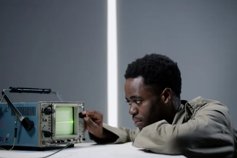
In 1965, engineers at Bell Laboratories were using rudimentary pulse-echo instruments to track down faults in telephone trunk lines buried beneath city streets. The technique was slow, the equipment filled a rack, and the results required careful interpretation. Six decades later, a network engineer at a Northern Virginia hyperscale facility can pull a handheld TDR unit from a tool bag, connect it to a suspect Cat6A run, and read a fault location to within a few centimeters — all before a trouble ticket has finished routing through the help desk system. The physics have not changed. The stakes have.
Time-Domain Reflectometry is, at its core, an application of a principle familiar to anyone who has shouted into a canyon and counted the seconds before the echo returned. A calibrated electrical pulse is injected into one end of a transmission line. When that pulse encounters a discontinuity — a crush, a bad termination, a corroded connector, a sudden change in dielectric material — a portion of its energy reflects back toward the source. By measuring the elapsed time between transmission and return, and knowing the velocity at which the pulse travels through the specific medium, the instrument calculates the precise distance to the discontinuity. The math is unforgiving in its simplicity: distance equals half the round-trip propagation time multiplied by the cable's nominal velocity of propagation (NVP).
The Physics of Impedance Mismatch
Every transmission line has a characteristic impedance determined by the geometry of its conductors and the properties of the surrounding dielectric. Standard Cat6A unshielded twisted-pair copper, for instance, is engineered to present 100 ohms across its operating bandwidth. When a TDR pulse travels down that cable and encounters a section where the impedance deviates from 100 ohms — because the cable has been kinked, because moisture has infiltrated the jacket, or because a punch-down block was terminated with the wrong technique — the reflection coefficient determines how much energy bounces back and in which polarity.
A positive reflection indicates an impedance increase: an open circuit, a break, or a severe crush that has separated conductors. A negative reflection indicates an impedance decrease: a short circuit, a bridged tap, or excessive capacitive loading from a poorly seated connector. The magnitude of the reflected waveform on the instrument's display correlates directly with the severity of the mismatch. An experienced engineer reads these signatures the way a radiologist reads a scan — each waveform morphology tells a specific story about the nature of the fault.
Velocity of propagation is the critical calibration variable. Solid polyethylene dielectric supports roughly 66 percent of the speed of light; foam polyethylene pushes that figure toward 78 to 85 percent. Entering the wrong NVP value into a TDR instrument produces a proportionally incorrect distance reading. Modern handheld units store NVP profiles for hundreds of cable types and allow field technicians to fine-tune the value against a known cable length — a step that takes under thirty seconds and eliminates the most common source of measurement error.
Why the Data Center Is Where TDR Earns Its Keep
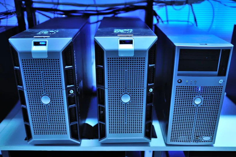
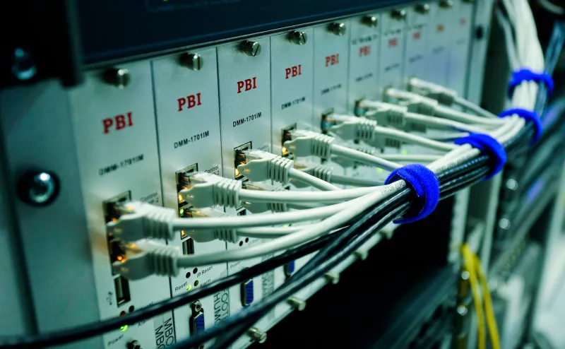
A hyperscale data center may contain tens of millions of individual cable segments. At facilities operated by major US cloud providers in markets like Ashburn, Virginia, or Phoenix, Arizona, structured cabling plants are engineered to support hundreds of thousands of server ports. When a link goes dark, the conventional diagnostic approach — systematically swapping cables, patch panels, and transceivers until the fault is isolated — can consume hours of labor and trigger cascading failures as adjacent circuits are disturbed in the process.
TDR collapses that process. A technician connects the instrument at the patch panel, injects a pulse, and within seconds receives a distance reading. If the fault is 47.3 meters from the panel, the engineer walks to the appropriate cable tray segment, inspects that specific location, and addresses the failure directly. No guesswork. No trial-and-error substitution. The instrument has already done the diagnostic work.
For fiber infrastructure, Optical Time-Domain Reflectometry (OTDR) applies the same principle using light pulses rather than electrical signals. Modern OTDR instruments can characterize splice losses, detect microbend events, and identify connector contamination along runs extending kilometers — a capability that becomes critical in campus-scale data center interconnects or dark fiber leased from metropolitan carriers.
Contrasting TDR with Frequency-Domain Alternatives
Vector Network Analyzers (VNAs) and frequency-domain cable certifiers offer complementary but distinct diagnostic capabilities. A VNA measures insertion loss, return loss, and impedance as a function of frequency — information that is essential for verifying that a cable plant meets the transmission specifications required by a given protocol. A cable certifier running a suite of TIA-568 tests confirms whether a link will support 10GBASE-T or 25GBASE-T operation. These are pass/fail qualification tools.
What frequency-domain instruments do not do well is answer the question of where. A return loss plot that shows degraded performance in the 200 to 400 MHz band tells an engineer that something is wrong somewhere in the link. It does not point to a specific location. TDR answers the location question directly and does so without requiring a sweep across dozens of frequency points. For fault isolation in an operational data center — where time is measured in dollars and the cable under test may be one of two hundred in a given bundle — the localization capability of TDR is not a convenience. It is the entire value proposition.
The two approaches are increasingly integrated in modern instruments. High-end cable analyzers from manufacturers such as Fluke Networks and IDEAL Industries now embed TDR functionality alongside full frequency-domain certification suites, allowing a single instrument to both qualify a new installation and localize faults in an existing one.
The Instrument in the Field
Conversations with network infrastructure engineers at US colocation and hyperscale facilities reveal a consistent pattern: TDR instruments are considered essential personal tools rather than shared lab equipment. Several engineers described scenarios where a handheld TDR unit had located a fault within minutes of a link failure, allowing physical repair to begin before a formal maintenance window was even scheduled.
One senior infrastructure engineer at a Tier IV facility in the Chicago metropolitan area described a case in which a 10-gigabit server link failed without apparent cause. The patch panel showed no visible damage, and the switch port reported a clean physical layer disconnect rather than a degraded signal. A TDR measurement identified an impedance anomaly at 23.6 meters — corresponding precisely to a point where the cable run passed through a cable tray that had been modified during an adjacent rack installation earlier that week. A staple had been driven through the cable jacket. Without TDR, that fault would have required pulling and replacing the entire 28-meter run under a change control process that would not have completed until the following maintenance window.
A Technique That Has Outlasted Its Era
The longevity of Time-Domain Reflectometry is not accidental. It persists because the underlying physics are both fundamental and practically useful. Transmission lines will always have characteristic impedances. Impedance discontinuities will always produce reflections. And the relationship between propagation velocity and elapsed time will always yield a calculable distance. No software update changes those facts.
As data center infrastructure grows denser and the cost of unplanned downtime continues to escalate, the ability to locate a fault in seconds rather than hours represents a measurable operational advantage. TDR does not require a network connection, a software license, or a cloud subscription. It requires a pulse, a cable, and a measurement. That combination has proven durable enough to survive from the Bell System era into the age of the hyperscaler — and there is no credible reason to expect that will change.